Version 2.2
INSTRUCTION MANUAL
MS8-36
MS8-62

Version 3.0 MS8-36 & MS8-62
2
INSTRUCTION MANUAL
Models: MS8-36, MS8-62
TABLE OF CONTENTS
1. Getting started.................................................................. .. 3
General......................................................................... 3
Installation................................................................... 3
Step by step operation............................................... . 3
2. Description of the Front Panel ............................................. 4
Process legends........................................................... 4
The main display........................................................... 5
The keyboard.................................................................. 7
3. Programming the Process Parameters................................... 7
Setting the program number............................................ 8
Entering process parameters............................................ 8
Entering continuos or immediate cycle............................. 9
Setting the cooling process parameters........................... 9
4. Programming the Time Parameters ....................................... 10
Updating the calendar............................................ 10
Programming the end cycle date.................................... 11

Version 3.0 MS8-36 & MS8-62
3
Contents (cont)
5. Operating Firing Cycle ............................................................ 11
Selecting the program number........................................ 11
Starting the firing cycle................................................... 12
Observing parameters while firing cycle......................... 12
Cycle completion............................................................. 12
The override.................................................................... 13
Power break during firing cycle....................................... 13
Stopping firing cycle......................................................... 13
6. Fault and Error messages ....................................................... 15
7. Example of programming procedure ........................................ 15
8. The Fume Exhaust Blower Outlet.......................................... 17
9. The special FAST program no 15 (FAST).............................. 17
10. The service program no 16 (SERVICE 16)........................... 17
Service program general description................................ 17
Starting service program................................................... 17
Programming the temp of the fume exhauster's Power Off 17
Programming the brightness of the VFD display.............. 17
Programming the language of displayed messages........... 17
Programming the degrees system Celsius or Fahrenheit.. 18
Leaving the service program........................................... 18
11. Instructions for personal safety.............................................. 19
12. Spare Parts…………………………………………………. 20
Version 3.0 MS8-36 & MS8-62
4
1 GETTING STARTED
1.1 General.
The new MS8-36 and MS8-62 CONTROLLER will store and remember 15 different programs
(preprogrammed by you) and will perform them accurately at your command:
The following sections will tell you how to program and operate the MS8-36 and MS8-62
CONTROLLER.
Please, take the time to be familiar with them.
ATTENTION!
ATTENTION!
Mount on non-flammable surface material only !
1.2 Installation
1.2.1 Remove all packing materials from around the furnace. Be sure to remove a wooden plank from
internal side of the door. (This wooden plank protects against transportation damages).
1.2.2 Connect the DOOR HANDLE by screwing it to the left or right side of the door (as convenient).
1.2.3 Install the CHIMNEY at the back of the furnace by inserting it into the big hole at the rear, while
the longer part of the pipe is upward. Fasten the unit, using supplied screws.
1.2.4 A Fume Exhauster can be connected to the special outlet, at the bottom-rear of a furnace.
This outlet provides 115 or 230V and protected by 2A fuse on the CPU board.
Note: Customers responsibility to verify the effect of the material introduced into the
furnace
In case of doubt customer should take precautions by asking for MSDS – Material Safety
Data Sheet.
The usage of an Extraction system (Fume Exhauster) is highly recommended.
1.2.5 Connect the power plug of the furnace to AC 230V or AC 115V. For Model MS8-62 connect
only to AC230V.
1.2.6 Switch ON the POWER (the switch located on the right side wall of a furnace).
Front panel will light up.
1.2.7 Your furnace is now ready for operation and programming (see following pages).

Version 3.0 MS8-36 & MS8-62
5
1.3 Step by step operation
1.3.1 Adjust the CALENDAR TIME (see chap. 4 - updating the calendar).
1.3.2 Select the program number, and the number of stages for this program (see chap. 3 - setting the
program number).
1.3.3 Program the heating parameters for selected program (see chap. 3 - entering process params).
1.3.4 Program END CYCLE DATE ( do this only if you wish to finish the program by specifying
day and time, otherwise skip this step, see chap.4).
1.3.5 Start the FIRING CYCLE (see chap. 5 - operating firing cycle).
1.3.6 Operate OVERRIDE if required (see chap. 5 - the override).
1.3.7 After the work will complete, stop the firing process by pressing the STOP pad.
1.3.8 Shut down the power switch (see chap5).
2. DESCRIPTION OF THE FRONT PANEL.
2.1 General
The MS8-36 and MS8062 CONTROLLER‘s front panel is a "friendly" system which was designed
according to the latest human engineering principles.
It is divided for your convenience into three areas:
Process Legends -- for graphical explanation of the process parameters.
Main display -- for displaying of process data and messages.
Keyboard -- for data entering and operating functions.
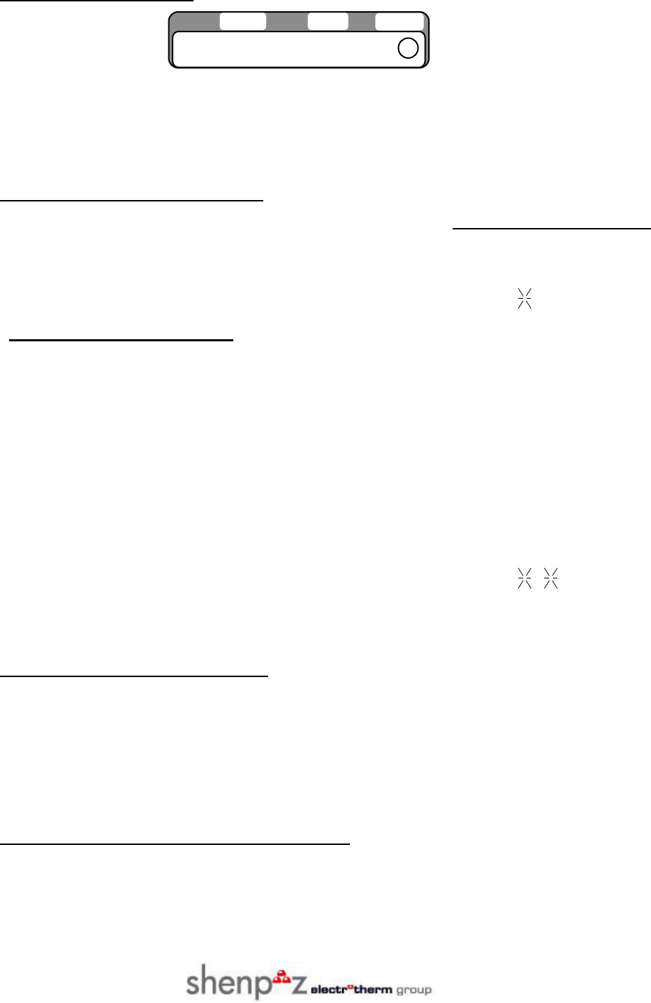
2.2 Process legends.
2.2.1 The Process Legends - are used for graphical explanation of the heating and cooling process
parameters, described as a curve with milestones like R , T ., H.
2.2.2 Process legends:
Each firing cycle program is build from programmable number of stages (1-8).
Each stage defined by:
R - HEAT RATE (c/min).
T - TEMPERATURE (c) set point.
H - SOAK TIME (min) period.
Except stages information, additional data must be programmed:

Version 3.0 MS8-36 & MS8-62
6
H End - total time from START to END (max 99 hours).
CONT / IMED- firing cycle termination mode: (programs 1-9 are permanently programmed as
continuous; 10-15 are User programmable for CONT or IMED).
CONT = CONTINUOUS, i.e. keeping the final temperature after firing cycle completion.
IMED = IMMEDIATE, i.e. shut off the heating at cycle end.
Version 3.0 MS8-36 & MS8-62
7
2.3 THE MAIN DISPLAY.
The main display consists of 10 alphanumeric characters. It is used to display different messages and
the HEAT ON condition.
Following is the summary of all the possible display messages:
START/STOP STATE MESSAGES
DISPLAYED EXAMPLES
2.3.1 STOP state (TIMER off) - temperature and time 0027C 08.30HR
2.3.2 STOP state (TIMER on) - temp, “timer on” sign, time. 0027C ^ 08.30HR
2.3.3 START state - actual temp, “GO” sign, remaining time. 0500C 01.34HR
: PROCESS DATA MESSAGES
2.3.5 R1-8: programmed heat rate R3 10 C/M
2.3.6 T1-8: programmed temperature T3 1050 C
2.3.7 H1-8: programmed soak time H3 99 MIN
2.3.4 H End - programmed total time HE 96.00 HR
2.3.8 CYCLE CONT - continuos cycle mode CYCLE CONT
2.3.9 CYCLE IMED - immediate cycle mode CYCLE IMED
2.3.10 PROG NO - program number display PROG NO 10
2.3.11 STAGES NO- total number of stages in program STAGES 03
2.3.12 END - override state 0850C END
2.3.13 H0 - delayed time to R1 start H0 42.00 HR
2.3.14 STAGE NUMBER-current stage in firing cycle STAGE 04
CALENDAR ADJUST MESSAGES
2.3.15 ADJ DAY - adjust calendar day ADJ DAY 20
2.3.16 ADJ HOUR adjust calendar hours ADJ HR 08
2.3.17 ADJ MIN - adjust calendar minutes ADJ MIN 30
2.3.18 ADJ MON - adjust calendar month ADJ MON 02
2.3.19 ADJ YAR - adjust calendar year ADJ YAR 97
END CYCLE DATE ADJUSTING MESSAGES
2.3.20 SET DAY - set required end cycle day SET DAY 20
2.3.21 SET HR - set required end cycle hour SET HR 09
2.3.22 SET MIN - set required end cycle minute SET MIN 15
TEMP.
TIME
HEAT ON

Version 3.0 MS8-36 & MS8-62
8
SERVICE PROGRAM MESSAGES
2.3.23 SERVICE program identification SERVICE 16
2.3.24 Code number service programming CODE NO 07
2.3.25 Temperature for fume exhauster top FAN 700
2.3.26 Display brightness BRIGHT 18
2.3.27 Display language ENGLISH
2.3.28 DEGREES Celsius or Fahrenheit DEG CELS
ERRORS AND DIAGNOSTICS MESSAGES
2.3.29 NO CURRENT fault NO CURRENT
2.3.30 TC BREAK- thermocouple break alarm TC BREAK
2.3.31 DATE ERROR - date set/adjust error DATE ERROR
2.3.32 TEMP FAULT - temp. sensing fault TEMP FAULT
2.3.33 OVER TEMP - over temp. warning OVER TEMP
2.3.34 EE ERROR - eprom data corrupted EE ERROR
NOTE: The stage numbers are referred as following:
1 -- First stage (R1, T1, and H1)
2 -- Second stage (R2, T2, H2,) e.t.c.
Version 3.0 MS8-36 & MS8-62
9
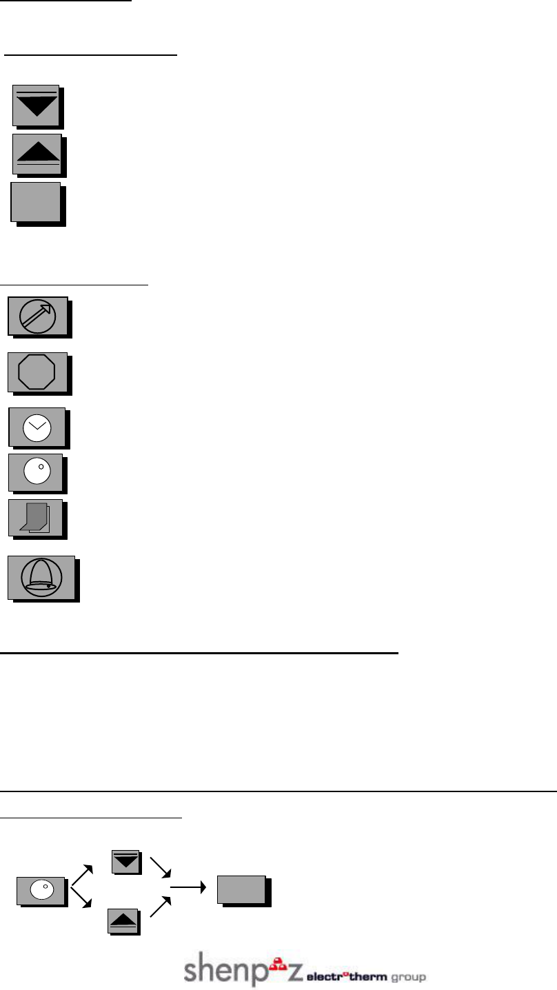
2.4 The keyboard.
2.4.1 The keyboard section includes 9 key-pads, functionally divided into two groups:
PROGRAMMING KEYS:
Used to decrease programmed values.
Used to increase programmed values.
Used to start programming and to confirm parameters for memory entry.
FUNCTIONS KEYS:
Starts firing cycle.
STOP Stops firing cycle.
Starts END CYCLE DATE programming .
Initiates PROGRAM and STAGE NUMBER select .
Starts CALENDAR updating.
Buzzer off, cancels audible alarm.
3. PROGRAMMING THE PROCESS PARAMETERS.
While programming, the display always shows the name of the current parameter and it's blinking
value. In those cases, when the displayed value is not blinking, it can not be changed and is shown
for information only.
3.1 Setting the program number and number of stages in the selected program.
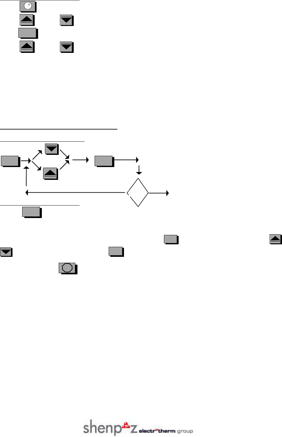
3.1.1 Shortened description:
Version 3.0 MS8-36 & MS8-62
01
3.1.2 Detailed description:
Press (PROGRAM N0). The MAIN DISPLAY will show current program number.
Press (+) or (-) to reach the desired value.
Press (ENTER) to confirm the value. The MAIN DISPLAY will show STAGES 01-08
Press (+) or (-) to select the desired number of stages for just selected program.
Please note that programs 0-9 are set by the factory to be "CONTINUOUS". Other programs have
programmable CONTINUOUS or IMMEDIATE firing cycle termination. (See also sec 3.3, entering
"CONTINUOS" or “IMMEDIATE" cycle).
3.2 Entering the process parameters.
3.2.1 Shortened description:
no yes STOP
3.2.2 Detailed description:
Press (ENTER) in order to start programming sequence for selected program.
The MAIN DISPLAY will show current R1 value.
If you are satisfied with the existing value, just press (ENTER.), otherwise, press (+) or
(-) to reach it, and then press (ENTER). Continue to program until last parameter will be
entered, then press STOP( STOP).
Please check that programming is completed i.e. the MAIN DISPLAY shows actual temperature and
time.
LAST?
Version 3.0 MS8-36 & MS8-62
00
There are two possible combinations of program sequences:
PROGRAMS 0-9: R1-T1-H1-.R2-T2-H2-R3-T3-H3-.......H-En d
PROGRAMS 10-15: R1-T1-H1.-R2-T2-H2-R3-T3-H3-......... H-End, CONT/IMED
In the case you wish to change only one parameter, you may reach it by pressing ( ENTER ),
until the main display will show its name. Then use (+) or (-) keys to change the value.
Return to idle by pressing ST0P (STOP).
NOTE for multi-stage programs, to save time you can press the ENTER pad few seconds, then the
display will advance automatically to further stages.
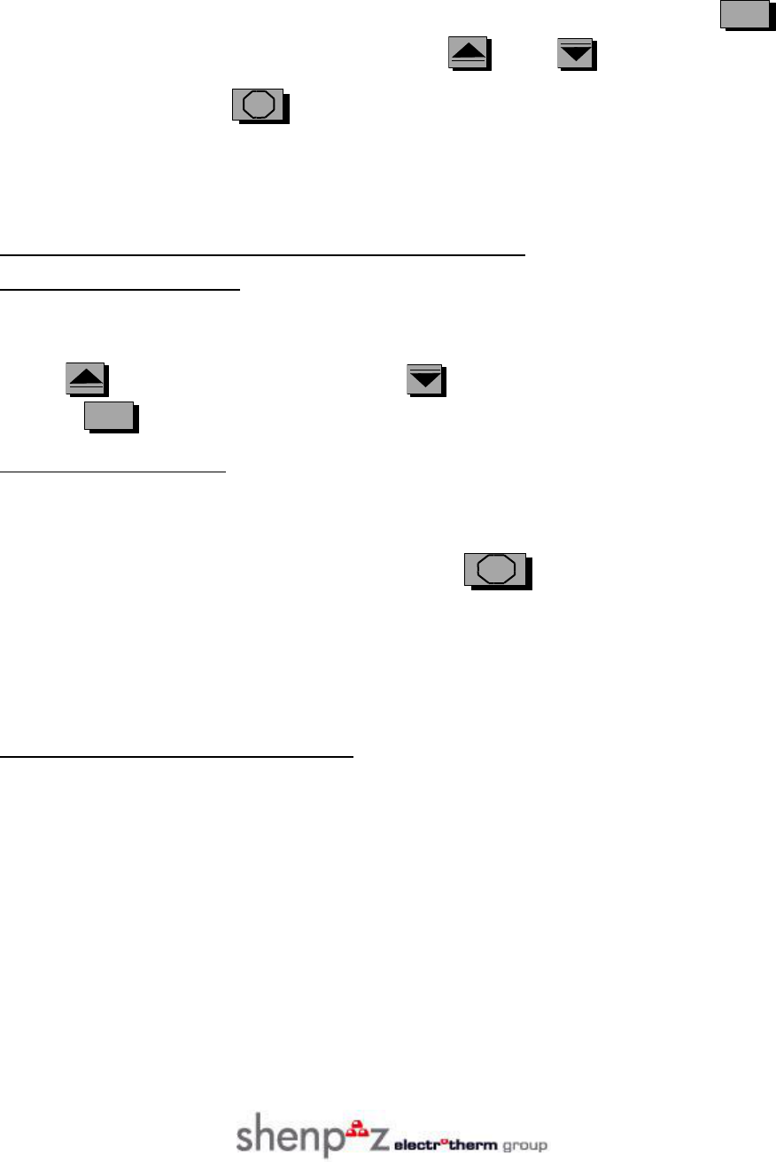
3.3 Entering "CONTINUOUS" or "IMMEDIATE" cycle.
3.3.1 Shortened description:
Reach the last parameter in programs 10-15.
The display will show CYCLE CONT or CYCLE IMED.
Press (+) for CONTINUOS mode, or (-) for IMMEDIATE mode, and confirm by
pressing (ENTER).
3.3.2 Detailed description:
There are two modes of firing cycle termination:
In the "CONTINUOS" mode, the furnace will maintain it's final temperature, after completion of the
cycle. Then it can be stopped manually by pressing STOP (STOP), or by switching Power OFF.
Programs 1-9 are by factory set to "continuos", other is programmable.
In the "IMMEDIATE" mode, the heating process is terminated immediately after cycle and the STOP
state is entered automatically.
To program CONT or IMED, see 3.3.1 (this page).
3.4 Setting cooling process parameters.
3.4.1 The design of the MS8-36 CONTROLLER software enables you to program a controlled
COOLING RATE. You may cool down the furnace to any required temperature and then heat it up
again.
3.4.2 “Cooling” means that the temperature is programmed to decrease with a defined rate. If the
programmed rate is faster then the natural temperature decrease of the furnace, then of course the
cooling will take more time than programmed.
3.4.3 To program cooling, set the temperature of the next stage to be lower then the current stage.
In this case R (the rate c/min) will be automatically taken as negative.
Version 3.0 MS8-36 & MS8-62
02
4. PROGRAMMING THE TIME PARAMETERS.
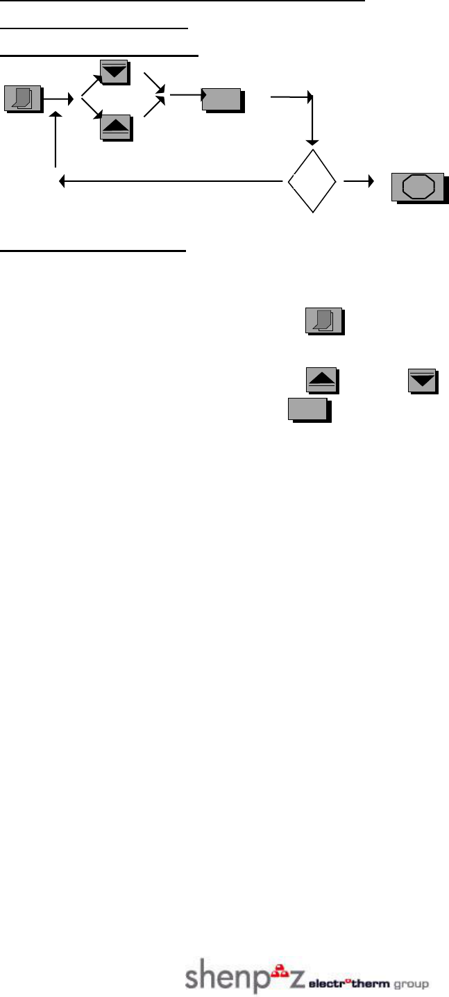
4.1 Updating the calendar.
4.1.1 Shortened description:
no yes STOP
4.1.2 Detailed description:
This procedure adjusts the DATE and TIME inside the MS8-36 and MS8-62 CONTROLLER to current
date and time. This is necessary when END CYCLE DATE attempted to be used.
To adjust the DATE and TIME, please press (CALENDAR).
The MAIN DISPLAY will show "ADJ DAY" label and its value.
If the date is incorrect, please adjust it using (+), or (-) pads.
When the required value is reached, press (ENTER).
Repeat the same procedure for HOURS, MINUTES, MONTHS and YEARS.
Finally the MAIN DISPLAY will return to ordinary STOP state showing updated time.
Remember, that YEARS are displayed in shortened form, i.e. only two last digits are shown (for year
1999 adjusts to 99, for 2000 adjust to 00).
LAST?
Version 3.0 MS8-36 & MS8-62
03
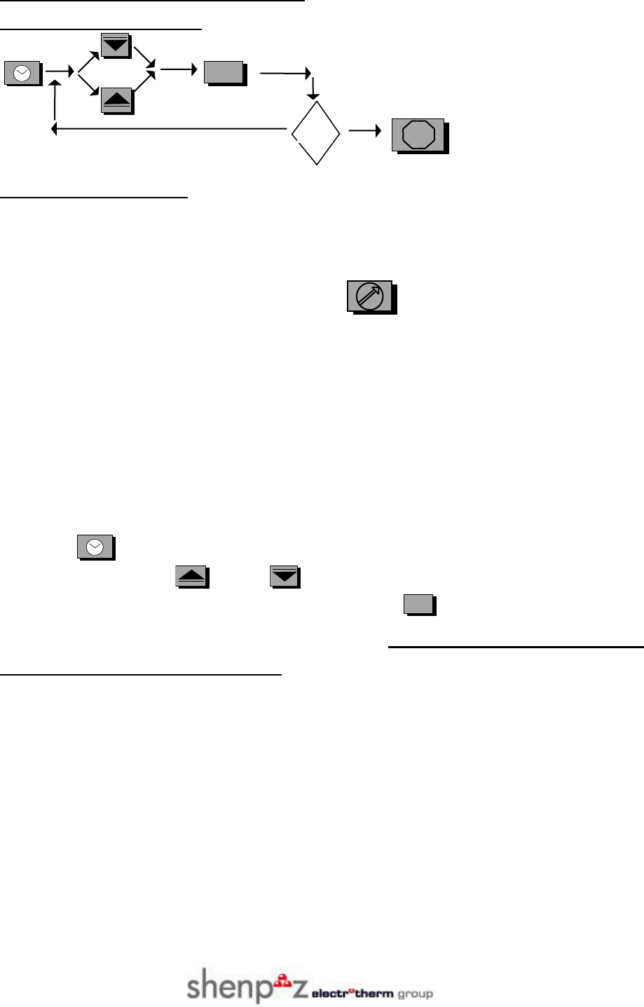
4.2 Programming the END CYCLE TIME.
4.2.1 Shortened description:
no yes STOP
4.2.2 Detailed description:
4.2.2.1 For your convenience, the total cycle time (total firing cycle time) can be programmed in one of
two ways:
By programming H End, using the procedure already described. (See 2.3.1). In this mode the value
H End is the required time period from pressing the (START) pad up to FIRING CYCLE end.
By setting the END CYCLE DATE. In this mode, you specify the day and the time you wish the
FIRING CYCLE will be complete. The MS8-36 and MS8-62 CONTROLLER will compute all the
necessary data, from pressing the START pad up to cycle termination.
The main difference between these two modes is that H End period is stored in the memory and can be
used again and again, but END CYCLE DATE can be used only once for the same setting.
4.2.2.2 To program the END CYCLE DATE, please do:
Check that the CALENDAR (actual) date and time is updated (see 4.1).
Press the (END CYCLE DATE) pad. The MAIN DISPLAY will show "SET DAY" message
and its value. Please use (+), or (-) pads to change the required day.
When required day is reached, please confirm by pressing (ENTER).
Repeat the same procedure for HOURS and MINUTES (at least one value must be changed,
otherwise the data will not be accepted).
Check that after last ENTER, the MAIN DISPLAY returns to STOP mode and shows special mark ^ in
between temperature and time. This mark ^ acknowledges that END CYCLE DATE is set. It means that
when START will be given, the cycle completion will be according to the END CYCLE DATE, just set.
(If this mark is not shown in the STOP state, it means that the firing cycle will complete accordingly to
the H End parameter).
To cancel the programmed timer mode (^ displayed), press START , and after a second, press
STOP (Another way to do this: just switch Power Off).
LAST?
Version 3.0 MS8-36 & MS8-62
04
5. OPERATING THE FIRING CYCLE
5.1 Selecting and observing the program number.
5.1.1 Before starting the firing cycle, please check and set (if required) the program number and
number of stages (see SETTING THE PROGRAM NUMBER).
The PROGRAM NUMBER (and number of stages) can be changed only in the STOP state, but can be
observed also during the firing cycle.
5.2 Starting the firing cycle.
5.2.1 Press (START) pad. The MS8-36 and MS8-62 CONTROLLER will respond by short
BEEP.
The MAIN DISPLAY will show the actual temperature and the value of the actual TIME will
interchange with REMAINING TIME, i.e. the time remained to the cycle end. (The remaining time is
periodically computed and displayed during the firing process).
Once you started the cycle - the furnace will heat up accurately and precisely according to the program
you have set, until reaching its end.
The rotating bar in the center of the MAIN DISPLAY will show that the firing cycle is running.
5.3 Observing process parameters during the firing cycle run.
5.3.1 Press (ENTER). The MAIN DISPLAY will show the STAGE NUMBER (see 2.3.14).
Continue to press (ENTER). With each new pressing, the MAIN DISPLAY will show the next
programmed parameter.
If for a few seconds no key will be pressed then the firing “on” message will be returned automatically.
5.4 Cycle completion
In the CONTINUOS mode:
After reaching the end of a cycle the MS8-36 and MS8-62 CONTROLLER will keep the furnace at the
final temperature. In this case, the MAIN DISPLAY will show actual temperature and the END message
including two rotating bars.
The alarm will buzz for about 60 seconds. After 5 and 10 minutes, it will buzz again. You can stop it
pressing (BUZZER OFF).
In IMMEDIATE mode:
After reaching the end of a cycle the MS8-36 and MS8-62 CONTROLLER will automatically stop the
heating process and enter STOP state.
Version 3.0 MS8-36 & MS8-62
05
5.5 The override.
5.5.1 The shortened description:
Check that you are in the final stage, or in END CYCLE mode ( END).
Press ENTER; observe that temperature parameter is shown.
Using (+), or (-), to increase or decrease the actual temperature and press
(ENTER). If you wish to change the last soak time, plse change it as required.
Remember that these changes are temporary and are valid only for the current firing process.
5.5.2 Detailed description:
5.5.2.1 The controller can be directed to change the actual temperature and soak time of the final part of
firing process.
This can be useful in cases when you didn't achieve the required results with the preprogrammed values,
or in any other applications, for example if you wish to cast two different metals in a single firing cycle.
5.5.2.2 In order to set the new values of T or H while furnace is in operation, just press
(ENTER):
The main display will show the current STAGE NUMBER.
If according the stage number you are in the final stage, press (ENTER) again. If now the
display shows temperature or time, you can program new values using (+), or (-) to
reach desired value and press (ENTER) to confirm.
(See programming).
5.5.2.3 These new values will be valid for the current firing cycle only and are not stored for further
cycles.
5.6 Power break during firing cycle.
5.6.1 In the case of power failure during firing cycle, the MS8-36 and MS8-62 CONTROLLER will
recover the latest working parameters and resume automatically the program operation. (In the final
"END CYCLE" state, any power brake will terminate heating process and enter the stop state).
5.7 Stopping firing cycle.
To stop the firing cycle at any time, press STOP (STOP), until short beep will be heard, and
MAIN DISPLAY will show the idle state.
Remember: if the cycle is not completed, you must STOP it before shutting down the MAIN POWER
SWITCH of the furnace, otherwise the program will be resumed after POWER ON.
Version 3.0 MS8-36 & MS8-62
06
6. FAULT AND ERROR MESSAGES.
6.1 Faulty conditions.
In case of faulty conditions, the MS8-36 and MS8-62 CONTROLLER will warn you, by activating
audible alarm, and displaying the error message.
The alarm can be stopped by pressing (BUZZER OFF), but the error message will remain until
(STOP) key will be pressed.
6.2 Fault messages
The following are the fault messages:
NO CURRENT- the current circuit is open. The reasons for this can be: heating elements burned, the
safety micro-switch is damaged or the door is opened when START was pressed.
TC BREAK - thermocouple break. The temperature sensing elements (located on the back of a muffle)
are burned or the TC plug is disconnected.
DATE ERROR - the END CYCLE DATE exceeds the 99 hour range (compared to the calendar date of
the MS8-CONTROLLER), or the last day of a month is incorrect. This message occurs when
(START) is pressed and incorrect END CYCLE DATE programmed (for example: 30 of February).
TEMP FAULT -temperature fault: the temperature sensing is abnormal mainly as a consequence of
shorted or unproperely installed thermocouple (for example: the + and the - are interchanged).
OVER TEMP - over temperature condition: the temperature in the muffle exceeded maximum limit
because of a fault.
EE ERROR - data corrupted. Reprogram current parameters.
7. EXAMPLE OF PROGRAMMING PROCEDURE FOR THREE STAGES PROGRAM
USING END CYCLE DATE.
The scenario: You wish to program and operate program no 5, three stages, to be complete at given date
and hour. The working parameters needed to be programmed as followed:
First stage: R1=8, T1=320, H1=45
Second stage: R2= 9, T2=500, H2=15
Third stage: R3= 9, T3=750, H3=45
Version 3.0 MS8-36 & MS8-62
07
7.1 Program and stages number set:
Press (PROG N0), press (+) or (-) till prog 5; press (ENTER)
Press (+) or (-) until 3-stage program is set, press (ENTER)
7.2 Process parameters programming.
Press (ENTER)
R1 displayed, press + or - till 8º C/M, press (ENTER)
T1 displayed, press + or - till 320º C, press (ENTER)
H1, displayed press + or - till 45 MIN, press (ENTER)
R2 displayed, press + or - till 9 Cº/M, press (ENTER)
T2 displayed, press + or - till 500º C, press (ENTER)
H2 displayed, press + or - till 15 MIN, press (ENTER)
R3 displayed, press + or - till 9º C/M, press (ENTER)
T3 displayed, press + or - till 750º C, press (ENTER)
H3 displayed, press + or - till 45 MIN, press (ENTER)
HE displayed (not important in this example), press (ENTER)
7.3 Check the calendar:
Press CALENDAR key pad
ADJ DAY displayed, update if required, press (ENTER)
ADJ HR displayed, update if required, press (ENTER)
ADJ MIN displayed, update if required, press (ENTER)
ADJ MON displayed, update if required, press (ENTER)
ADJ YAR displayed, update if required, press (ENTER)
7.4 Set the END CYCLE DATE.
Press (END CYCLE DATE) pad. SET DAY will be displayed.
Press + or - till required day will be displayed, press (ENTER), SET HR will be displayed.
Press + or - till required hour will be displayed, press (ENTER), SET MIN will be displayed
Press + or - till required minute will be displayed, press (ENTER)
Observe that normal IDLE state display shown with ^ mark in its center.
Now you are ready to start the firing cycle by pressing (START) pad.

Version 3.0 MS8-36 & MS8-62
08
8. THE FUME EXHAUST BLOWER OUTLET.
8. 1 General.
8.1.1 The fume exhaust BLOWER outlet provides the ability to connect an external exhauster to the
special power socket located on the rear-bottom of the furnace.
The power to this socket is applied when the temperature inside the furnace reaches 100 deg Celsius,
and removed according preprogrammed temperature in service program 16 (FAN).
9. FAST PROGRAM NO 15 (One stage).
9.1 There are cases, when required single stage timesaving burnout program with fastest possible
heat rate.
For this requirement, one stage program (no 15) is available for use. The only parameters you
need to enter while programming this case are: final temperature and time (T1 and H1).
10 SERVICE PROGRAM NO 16 (SERVICE 16).
10.1 Service program general description.
10.1.1 Using this program, it is convenient to change some parameters of the furnace:
The temperature in which the fume exhauster is powered off,
The brightness of the VFD display,
The language of displayed messages,
The degrees representation: Celsius of Fahrenheit.
10.2 Starting service program.
plse select program no 16. SERVICE 16 will be displayed
plse press ENTER twice. CODE NO will be displayed
use (+) or (-) to reach CODE NO 07
plse press ENTER FAN 700C message will be displayed.
NOTE: the CODE 07 must be entered, to prevent access to the service program without reading
this text.
10.3 Programming the temperature in which the fume exhauster is powered off:
plse reach screen FAN 700C, as described in sec 9.2
use (+) or (-) to select desired temperature
plse press ENTER. BRIGHT message will be displayed
10.4 Programming the brightness of the VFD display.
plse reach screen BRIGHT (as described in 9.3).
use (+) or (-) to reach minimum brightness 12, max brightness 31.
plse press ENTER. ENGLISH (or other language will be displayed,
NOTE: The new brightness will be active, only after release of (+ ) or (-) keys.
10.5 Programming the language of displayed messages.
plse reach screen ENGLISH (or other language) as described in 9.4
use (+) or (-) to select ENGLISH,DEUTCH,FRENCH OR ITALIAN
plse press ENTER. DEG CELS (or FAHR) will be displayed.

Version 3.0 MS8-36 & MS8-62
09
10.6 Programming the degrees representation: Celsius of Fahrenheit.
plse reach screen DEG CELS (or FAHR ) according 9.5
press (+) or (-) to select CELS or FAHR
plse press ENTER. stop state screen will be displayed.
10.7 Leaving the service program.
plse press ENTER CODE NO 07 will be displayed
use (-) to reach CODE NO 00
plse press ENTER stop state screen will be displayed, and program number
will be automatically changed to 1.
(another way of leaving service program: from the stop screen choose desired program ).
NOTE: if for some reason you try to operate firing cycle while service program is still selected,
the furnace will respond by message "SERVICE 16".
CAUTION!!! VERY IMPORTANT: IN ANY CASE OF THE ASSEMBLY
/DISASSEMBLY OF THE CONTROL PANEL (OR OTHER MODULES OF THE
FURNACE) , DISCONNECT FIRST THE AC POWER SOURCE.

Version 3.0 MS8-36 & MS8-62
21
11. Instructions for personal safety of MS8-36 and MS8-62 users.
CAUTION!!! VERY IMPORTANT: IN ANY CASE OF THE ASSEMBLY
/DISASSEMBLY OF THE CONTROL PANEL (OR OTHER MODULES OF THE
FURNACE) , DISCONNECT FIRST THE AC POWER SOURCE.
Industrial furnaces provide compliance with internationally accepted Safety Regulations prior of being
licensed as a marketable item. As a consequence, modern industrial furnaces are highly reliable and safe
machines.
Nevertheless, operator's misuse of such furnaces may bring about some hazards:
It may cause burns on limbs due to the OPERATOR if not using proper tweezers or breaching one or more
of the most basic self preservation work rules.
It may expose the OPERATOR to electric shock if routine electrical and mechanical checks were not
performed on it.
It might start a fire if combustible materials are held in close proximity to the furnace door or walls.
Care should be taken to secure the furnace-door, in one of its two stable positions, during materials
handling.
The furnace should be placed on a fireproof topped, mechanically stable, table. The table should be
placed alongside a power receptacle carrying wall, the furnace back-panel towards that wall. The furnace
power ON/OFF switch must be always accessible
to the user.
The operator should approach the furnace from the front-door side only, up to a distance of 30 / 35 cm
from that door and have useable table areas to the left and right of the furnace, NOT in front of the
furnace.
No combustible materials or liquids should be stored within 1 meter, at least, from the furnace. Before
placing any unfamiliar material inside the furnace, the operator should validate the material’s flammability
ratings.
Cleaning:
a) Turn off the furnace from the main switch (located on the rear panel.
b) Disconnect the furnace from the electricity. In case the furnace's surface is
hot – leave it unplugged until the furnace would cool down completely.
c) Clean the furnace using dry cloth only.
d) DO NOT clean the furnace using any cleaning agents, but dry cloth
only.
Version 3.0 MS8-36 & MS8-62
20
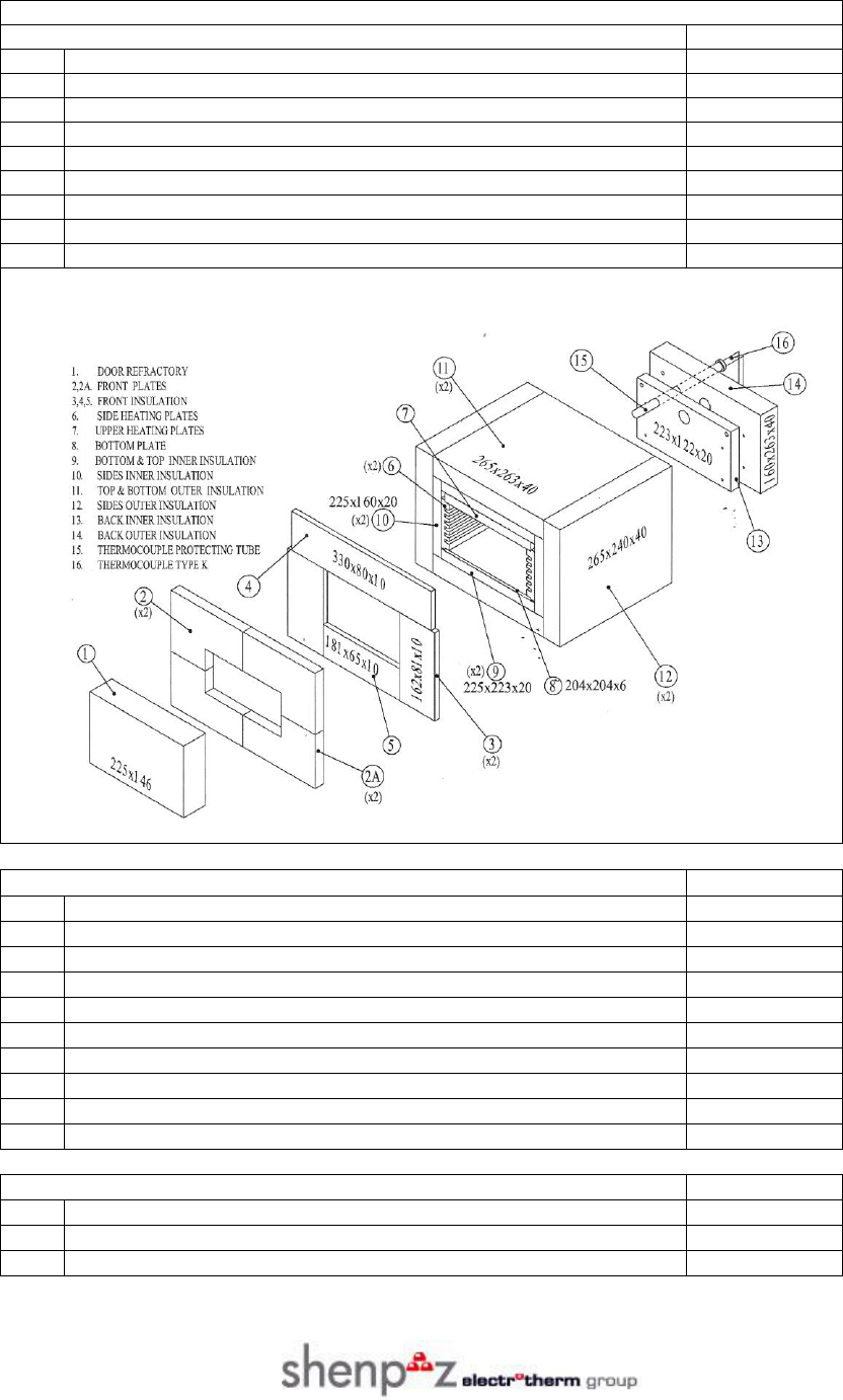
SPARE PARTS LIST MS8-36
REFRACTORIES
Part No.
1
Door Refractory
ZVD03BI
6-7
Heater plates with elements-set
MFG51BI
8
Bottom plate
MFG21BI
9
Bottom & top inner insulation ( 2 pcs )
MFG19BI
10
Side inner insulation ( 2 pcs)
MFG20BI
11
Bottom & top outer insulation (2 pcs )
MFG16BI
12
Side outer insulation (2 pcs )
MFG17BI
13
Back inner insulation
MFG18BI
14
Back outer insulation
MFG15BI
15
Thermocouple protecting tube for – 36/62
MFG01BI
ELECTRICAL PARTS
Part No.
16
Thermocouple ( type K ) for 36/62
AMB01BI
17
Safety switch for 36/62
ECG02BI
18
Main switch
ECG01BI
19
Triac 25A for 36/62
DIG01BI
20
Complete temp. control panel MS8-36
ABF02BI
21
Main board MS8-36
ABC01BI
22
Display board for MS8-36/62
ABD01BI
23
Touch switch control panel MS8-36/62
KBR01BI
24
Power input socket + fuse 10A
CNJ02BI
25
Line cord (continental Europe / England)
WRR04BI
TRADE-IN EXCHANGE FOR REPLACEMENT ITEMS
Part No.
Complete temp. control panel MS8-36/62
ABF02BI
Main board MS8-36
ABC01BI
Display board MS8-36
ABD01BI
Version 3.0 MS8-36 & MS8-62
22
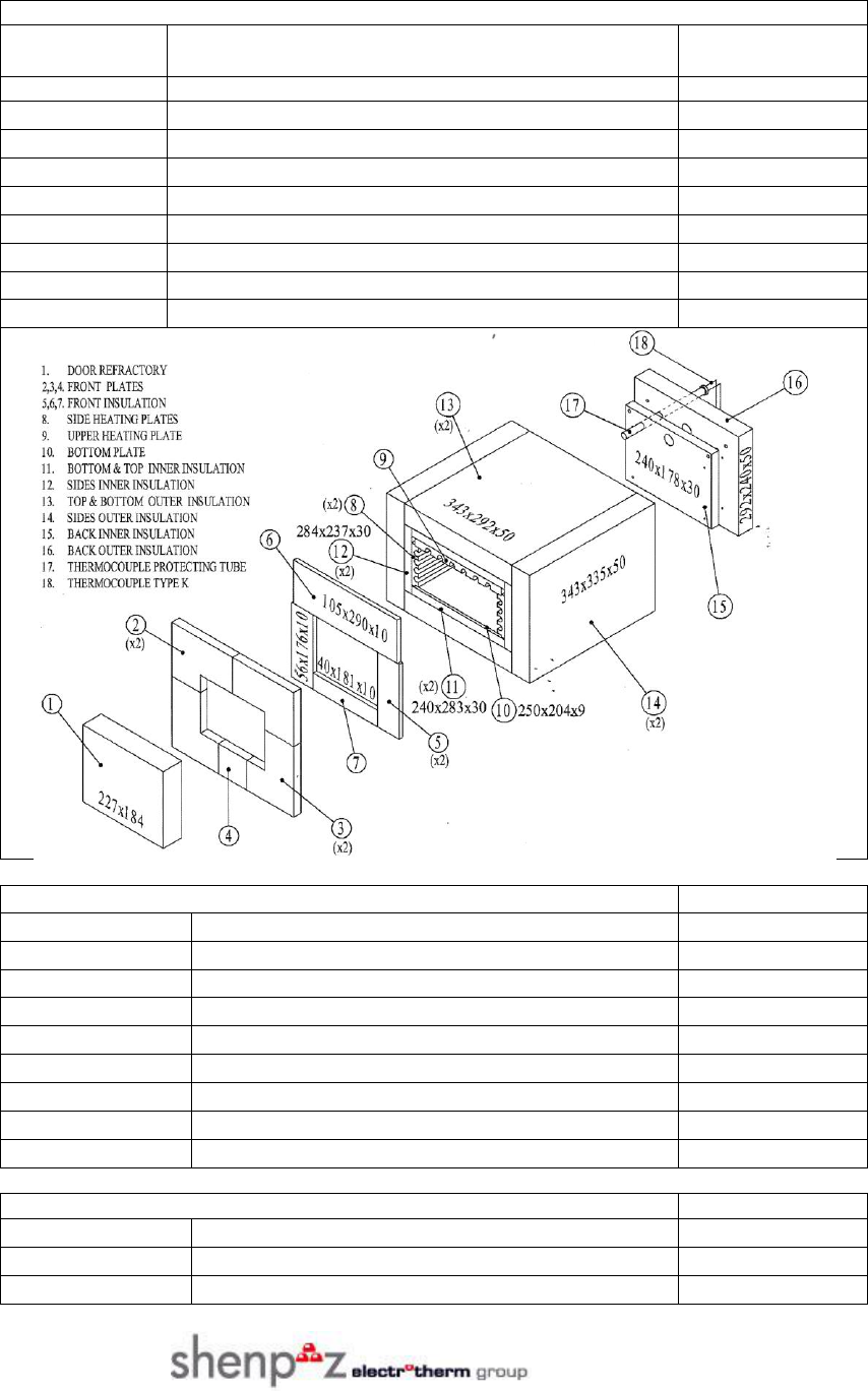
SPARE PARTS - MS8-62
REFRACTORIES
1-MBR13BI
Door Refractory
8-9MFG50BI
Heater plates with elements – set 3 pcs.
10-MFG37BI
Bottom plate
11-MFG35BI
Bottom & top inner insulation 2 pcs.
12-MFG36BI
Sides inner insulation 2 pcs
13-MFG32BI
Bottom & top outer insulation 2 pcs
14-MFG33BI
Sides outer insulation 2 pcs.
15-MFG34BI
Back inner insulation
16-MFG31BI
Back outer insulation
17-MFG01BI
Thermocouple protecting tube
ELECTRICAL PARTS
18-AMB01BI
Thermocouple (type K ) for 36/62
ECG02BI
Safety switch for 36/62
ECG01BI
Main switch
DIG01BI
Triac 25 A for 36/62
ABG02BI
Complete temp. control panel MS8-62
ABC01BI
Main board MS8-62
ABD01BI
Display board for MS8 36/62
KBR01BI
Touch switch control panel MS8-36/62
ECF02BI
Fuse holder + fuse 15A
TRADE-IN EXCHANGE FOR REPLACEMENT ITEMS
ABG02BI
Complete temp. control panel MS8-62
ABC01BI
Main board MS8-62
ABD01BI
Display board for MS8 36/62

Version 3.0 MS8-36 & MS8-62
23
We thank you for choosing the MS8-36 or MS8-62 laboratory burnout furnace.
For any questions or additional support, please contact us and we will look forward to assisting you.
Electrotherm Marketing – ShenPaz Technologies
5 HaTasia Street, Ramat Gabriel Industrial Park
Migdal HaEmek
Phone: +972 (04) 6666902 or +972 (03) 562 0428
Fax: +972 (04) 6042040
Email: lior@shenpaz.com
www.shenpaz.com
